This is an old revision of the document!
Table of Contents
SPACAR Light
Getting started
Before delving into the exact MATLAB syntax for running a simulation, it's good to consider the concept of a flexible multibody model and how SPACAR Light ties into that.
Flexible multibody model
In general, a multibody model is a collection of bodies that are interconnected. Such a model typically represents a mechanism, a linkage or a structure. The bodies could be fully rigid, or have some flexibility. The points of interconnection typically represent the joints (revolute joint, spherical joint, etc.) or contact points of the system.
 | 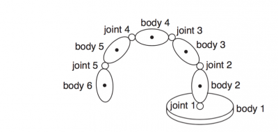 |
| Example of a serial robot arm [1] | Schematic multibody model [2] |
With a description of the geometry of the bodies, the material properties, and some kind of input to the model, the behavior of the entire multibody model can be simulated. This way, the actual system that the multibody model represents can be analyzed in terms of e.g.
- kinematics (position, velocity and acceleration),
- statics (deflection and stress due to applied forces),
- natural frequencies and buckling loads, and
- fully time-dependent dynamic behavior.
Elements and nodes
In SPACAR (as in most other finite element and multibody software), the bodies are usually referred to as elements, and the points of interconnection as nodes. The full version of SPACAR features a range of different elements for modeling a variety of systems. While powerful, this does increase the complexity of creating a model.
In SPACAR Light, we're only considering one type of element: the 3-D flexible beam element. Also, the type of analysis is only going to be static (including natural frequencies and buckling loads). Both choices are well suited to the analysis of flexure mechanisms and reduce complexity for the user.
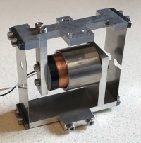 | 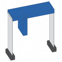 | 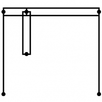 |
| Parallel flexure mechanism | Drawing | Schematic multibody model |
General usage
When SPACAR Light is installed correctly, it is typically invoked using the MATLAB command
out = spacarlight(nodes,elements,nprops,eprops)
With the basic concept of a multibody model outlined above, this command is already very revealing; it shows that the user has to provide four inputs:
- Coordinates of the nodes in
nodes - Elements that connect the nodes in
elements - Node properties (such as boundary conditions, applied loads and inertia) in
nprops - Sets of element properties (such as dimensions, material constants and flexibility) in
eprops
Generally, these input argument are straight-forward. On the following pages, each input will be detailed. There is a walkthrough example in which all steps towards a simulation are explained. For complete reference, the full syntax list provides details of each field and property. Additional examples of models are also available.
References
1: staubli.com (Stäubli TX2-90 Product leaflet)
2: lecture slides Dynamics of Machines, J.B. Jonker, R.G.K.M. Aarts