This is an old revision of the document!
Table of Contents
SPACAR Light
Example: modeling inertia properties of oddly-shaped rigid bodies
Dynamic behavior of arbitrarily-shaped (rigid) objects can be modeled in Spacar simulations by using the nprops(i).mass and nprops(i).mominertia input fields. This example shows how to correctly include in SPACAR Light the mass and moment of mass (mass moment of inertia) properties of an oddly-shaped CAD object from SolidWorks. Note that we assume that the object is rigid; its elastic behavior is not taken into account here.
The procedure consists of two steps. First, we obtain the relevant properties from SolidWorks. Second, we add the properties to the SPACAR Light script.
The basic idea
In Spacar, we can create a dynamically equivalent model of an arbitrarily-shaped rigid object by means of just a single node with specific properties:
- This node has to be located at the center of mass of the object
- The mass of the object has to be lumped to this node
- The moment of mass of the object has to be lumped to this node
- (The components of the moment of mass have to be computed with respect to the center of mass and aligned with the global frame of Spacar)
Obtaining mass and inertia properties from SolidWorks
First, we need to apply a material to the SolidWorks part in order to account for the object's density. This can be done by right clicking on “Material” in the design tree and selecting the correct material.
Next, a coordinate system has to be created which is aligned with the global coordinate system used in the Spacar simulation (the default coordinate system in SolidWorks is likely to be different from the one in your Spacar model). It is crucial that the orientation of the coordinate system in SolidWorks and Spacar is identical. While the position of the origins can be different (the inertia properties are calculated with respect to the center of mass anyway), it is recommended that the origin of the new coordinate system in SolidWorks coincides with at least a point that is also a node in the Spacar model (in order to deal with the position of the center of mass). If needed, a custom reference point can be created from a sketch node or with: SolidWorks ⇒ Features ⇒ Reference Geometry ⇒ Point.
To define the orientation of this new coordinate system, two perpendicular edges/lines/axes are required which are aligned with the x-, y- or z-axis of the Spacar model (the third one follows automatically).
In this example, two reference axes are used (SolidWorks ⇒ Features ⇒ Reference Geometry ⇒ Axis). The first SolidWorks axis is aligned with the x-axis of the Spacar model, defined by the intersection of the Front Plane and Top Plane. The second SolidWorks axis is aligned with the y-axis of the Spacar model, defined by the intersection of the Right Plane and Top Plane.
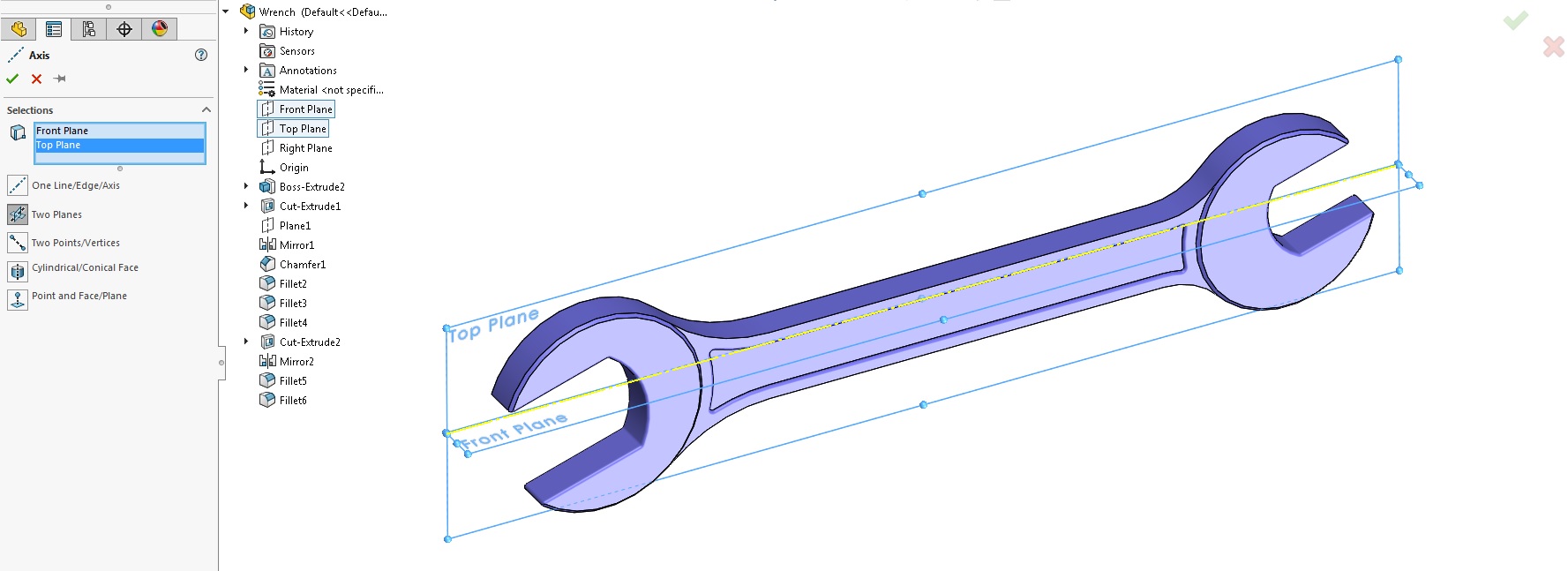
Next, a new coordinate system is made (SolidWorks ⇒ Features ⇒ Reference Geometry ⇒ Coordinate system) and the axes generated in the previous step are selected for the x- and y-axis of this coordinate system.
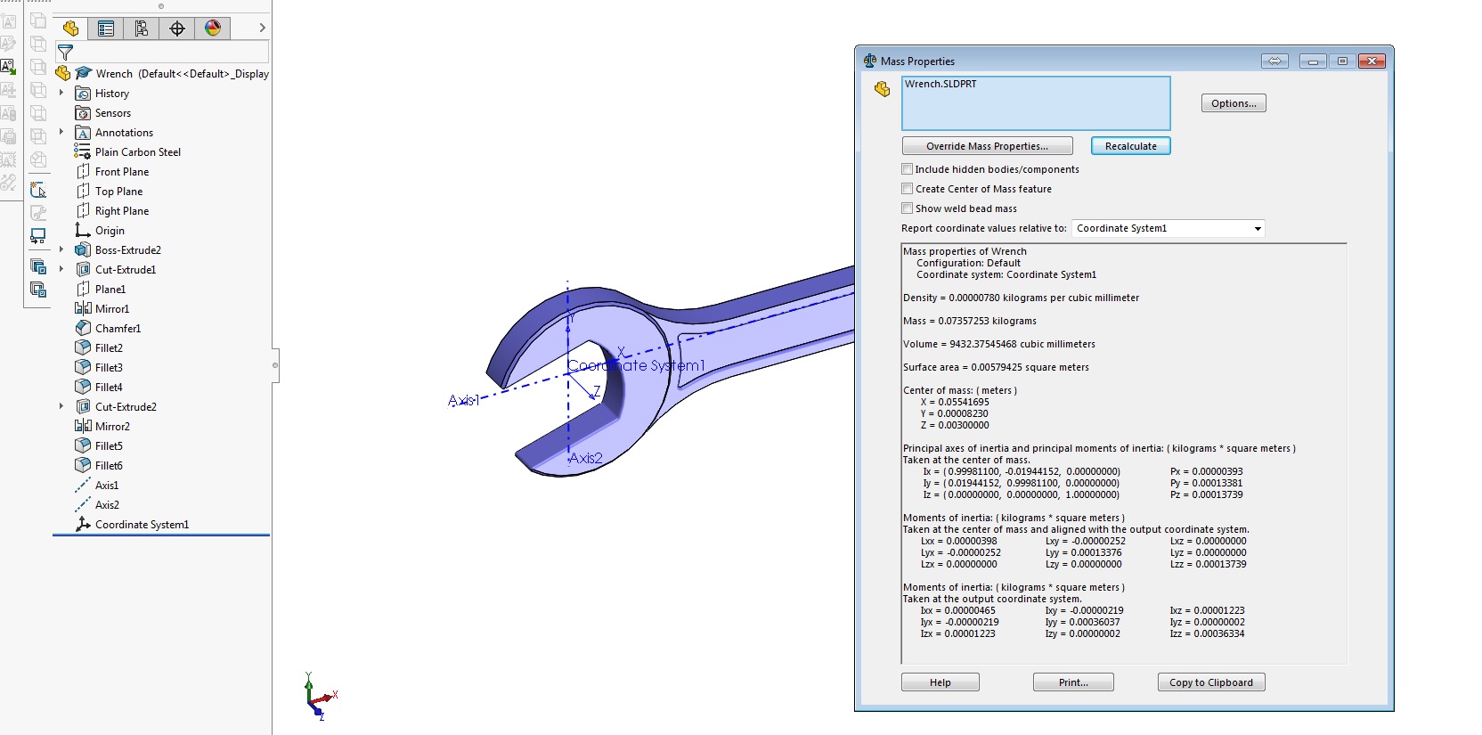
Lastly, the inertia properties can be obtained from: SolidWorks ⇒ Evaluate ⇒ Mass Properties. Here, we have to specify the generated coordinate system from the previous step at “Report coordinate values relative to:”. The units and number of decimals can be changed with the “option” button (for SPACAR Light, the values in kgm2 are required). Take note of
- the total mass of the object
- the moments of inertia taken at the center of mass and aligned with the output coordinate system.
- the position of the center of mass (note: this position is provided with respect to the selected coordinate system)
Adding mass and inertia properties to Spacar
For this example a single leafsprings is simulated between node 1 ([0,0,0]) and node 2 ([0 0.1 0]), with one end of the wrench attached to node 2 (which coincides with the position of the coordinate system in SolidWorks). Furthermore, a third node at the center of mass of the wrench ([0.055 0.1 0.003]) is rigidly connected to node 2. At this node in the center of mass of the wrench, both the mass and moment of mass properties are added with the nprops(i).mass and nprops(i).mominertia fields. Check the full syntax list for the correct use of nprops(i).mominertia because the definition differs from SolidWorks. nprops(i).mominertia consists of a vector with length six, [Ixx Ixy Ixz Iyy Iyz Izz] in kgm2. Note the tensor components are needed, so Ixy, Ixz and Iyz represent the negative of the products of inertia (which are provided by SolidWorks).
A visualization of the first two vibration modes of this system is provided below. In order to provide a clearer image of this system, the CAD file of the wrench is included in the visualization. The visualization of CAD files in Spacar is outside of the scope of this example and therefore not discussed. The MATLAB code of this example is provided at the end of this page.


- inertia_example.m
% EXAMPLE SCRIPT
% This example simulates the mass and inertia of a wrench attached to a leafspring
clc
clear

%% NODE POSITIONS
%           x y z
nodes = [   0 0 0;              %node 1
            0 0.1 0;            %node 2
            0.055 0.1 0.003];  %node 3

%% ELEMENT CONNECTIVITY
%               p   q
elements = [    1   2;  %element 1
                2   3]; %element 2


%% NODE PROPERTIES
%node 1
nprops(1).fix                = true;         %Fix node 1
nprops(3).mass               = 0.074;        %0.74Kg at the center of mass
nprops(3).mominertia         = [ 0.00000398 0.00000252 0.0000000 0.00013376 0.00000000 0.00013739]; %Inertia at the center of mass

%% ELEMENT PROPERTIES
%Property set 1
eprops(1).elems    = 1;            %Add this set of properties to elements 1 and 3
eprops(1).emod     = 210e9;            %E-modulus [Pa]
eprops(1).smod     = 70e9;             %G-modulus [Pa]
eprops(1).dens     = 7800;             %Density [kg/m^3]
eprops(1).cshape   = 'rect';           %Rectangular cross-section
eprops(1).dim      = [30e-3 0.3e-3];   %Width: 50 mm, thickness: 0.2 mm
eprops(1).orien    = [0 0 1];          %Orientation of the cross-section as a vector pointing along "width-direction"
eprops(1).nbeams   = 1;                %4 beam elements for simulating these elements
eprops(1).flex     = 1:6;        	   %Model out-of-plane bending (modes 3 and 4) as flexible
eprops(1).color    = 'grey';
eprops(1).opacity  = 0.7;

%Property set 2
eprops(2).elems    = 2;                %Add this set of properties to element 2
eprops(2).orien    = [0 0 1];          %Orientation of the cross-section as a vector pointing along "width-direction"
eprops(2).hide     = true;           %Hide element (in visualization only)

%% SIMULATION
out1 = spacarlight(nodes, elements, nprops, eprops);