This is an old revision of the document!
simulation of parallel flexure guide
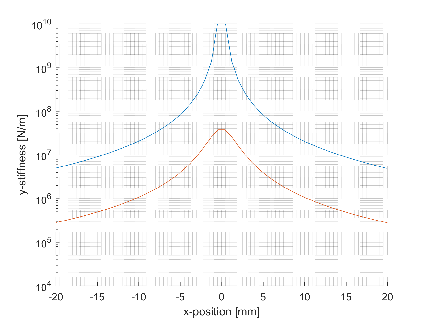
This example shows the static simulation of a parallel flexure guide which moves from -20mm deflection up to 20mm deflection in x-direction (the degree of freedom of the parallel flexure guide). Goal is to evaluate the translational stiffness in the supporting directions (y- and z-direction) of the end-effector over the range of motion.
The figure bellow provides the stiffness values over the entire range. It can be clearly seen that with increasing deflection, support stiffness drops. Furthermore, the initial stiffness in y-direction is infinite as only the out-of-plane bending and torsion deformations are considered.
An example file for providing the input for Spacar Light is provided bellow for download.
- pfg_example.m
clear
clc


%% NODE POSITIONS
nodes = [-50E-3 0.0 0;      %node 1
         -50e-3 100e-3 0    %node 2
         0 100e-3 0         %node 3
         50e-3 100e-3 0     %node 4
         50e-3 0 0];        %node 2


%% ELEMENT CONNECTIVITY
elements = [1 2             %element 1: 1st leafspring
            2 3             %element 2: 1st half of rigid body
            3 4             %element 3: 2nd half of rigid body
            4 5];           %element 4: 2nd leafspring


%% NODE PROPERTIES
nprops(1).fix = true;       %fix begin 1st leafspring
nprops(5).fix = true;       %fix end 2nd leafspring

nprops(3).force = [0 -10 0]; %load of 10N on node 3 y-direction
nprops(3).mass = 1;         %1kg mass at node 3
nprops(3).displ_initial_x = -20e-3; %initial displacement, node 3 -20mm moved in x
nprops(3).displ_x = 40e-3;  %additional displacement, node 3 40mm moved in x


%% ELEMENT PROPERTIES
eprops(1).elems = [1 4];    %both leafsprings
eprops(1).emod = 210e9;     %E-mod steel
eprops(1).smod = 70e9;      %G-mod steel
eprops(1).dens = 7800;      %rho steel
eprops(1).dim = [30e-3 0.5e-3];
eprops(1).cshape = 'rect';
eprops(1).flex = [2 3 4];   %bending and torsion flexible
eprops(1).orien = [0 0 1];
eprops(1).nbeams = 2;       %2 beams for simulation

eprops(2).elems = [2 3];    %end-effector
eprops(2).dens = 2700;      %rho alluminium
eprops(2).dim = [30e-3 10e-3];
eprops(2).cshape = 'rect';
eprops(2).orien = [0 0 1];
eprops(2).color = [1 0 0];  %red color


%% RELEASES
rls(1).def = [2 3 4 5 6];
rls(4).def = [3 4];

%% OPTIONAL
opt.gravity = [0 0 -9.81];  %gravity in z-direction
opt.loadsteps = 50;

%% DO SIMULATION
out = spacarlight(nodes,elements,nprops,eprops,rls,opt);

%Plot stiffness values over the range of motion
Ky(:) = 1./out.node(3).CMglob(2,2,:); %Y stiffness evaluated at node 3
Kz(:) = 1./out.node(3).CMglob(3,3,:); %Z stiffness evaluated at node 3
x = out.node(3).p(1,:).*1000;         %Position of the end-effector in mm (.*1000)

fig1 = figure;
hold on
plot(x,Ky)
plot(x,Kz)
grid minor
xlabel('x-position [mm]')
ylabel('y-stiffness [N/m]')
fig1.Children.YScale = 'log'        %plot with log yscale
fig1.Children.YLim = [1e4 1e10]